Protection Against Exceeding Cable Limiting Temperature
How to calculate the time it takes for a cable to reach its limiting temperature.
BS 7671 434.5.2: A fault occurring at any point in a circuit shall be interrupted (disconnected) within a time such that the fault current does not cause the permitted temperature of any conductor or cable to be exceeded.
434.1 – Determination of prospective fault current: The prospective fault current shall be determined at every relevant point of the installation. This shall be done by calculation, measurement or by enquiry.
Calculate the time it takes for a cable to reach its limiting temperature for a given fault current.
To calculate how long a cable or conductor will take to reach its limiting temperature, as an approximation we can use the following formula, (k²) x (S²) / (I²) ÷ 1000 ÷ 1000 = t
- t = Time in Seconds
- S = Conductor Size (mm²)
- k = Conductor k Value
- I = Effective Fault Current (kA)
If using Amps (rather than kA) as the fault current value (I) then the equation is slightly different,
t = (k²) x (S²) ÷ (I²) (where I = Amps).
t = (k²) x (S²) ÷ (I²) ÷ 1000 ÷ 1000 (where I = kiloamps).
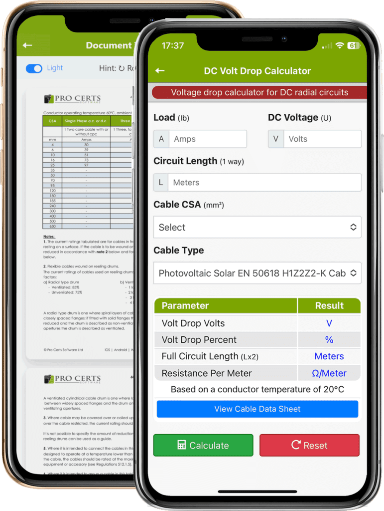
Cable Temperature Rise Time Calculator
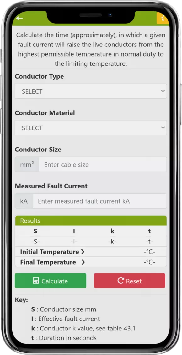
Our Electrical Tools and Reference app already includes this new Cable Temperature Rise Time Calculator and can be found under the main Tools menu.
The electrical industry consensus seems to be the measurement method (where possible & safe to do so) is preferred. The by enquiry method is relying on a 3rd party’s information being correct which could be out of date. The calculation method leaves room for calculation errors.
To check compliance with 434.5.2 we need to calculate the time in which a given fault current will raise the live conductors temperature from the highest permissible temperature (in normal use) to the limiting temperature.
We then need to compare that calculated time against the actual circuit disconnection time to ensure the actual disconnection time is less than the calculated time it will take for the conductor or cable to reach the limiting temperature.
If a circuit disconnection time is greater (longer) than the time it takes for a cable or conductor to reach its limiting temperature then damage to the cable or conductor will occur because the limiting temperature of the conductor and/or cable will be exceeded.
Conductor k Values
Common conductor k values can be obtained from BS 7671 table 43.1, further values of k can be found in BS 7454 Method for calculation of thermally permissible short-circuit currents, taking into account non-adiabatic heating effects.
Values of k for common materials, for calculation of the effects of fault current for disconnection times up to 5 seconds can be found in table 43.1 of BS 7671.
A conductor k value varies between cable types and size such as conductor insulations Thermoplastic, Thermosetting or Mineral Insulated.
Conductor k values can be calculated using the formula from IEC 60364.5.54
Fault Current Thermal Protection
When designing a new circuit or inspecting an existing circuit we need to ensure that the limiting temperature of the cables and conductors will not be exceeded under a circuit fault condition.
Under fault conditions the conductor temperature will rise, there is a limit to what the cable is capable of rising to before causing damage, this is called the cable limiting temperature, not to be confused with the cable operating temperature.
Cable Limiting Temperature
A cable limiting temperature is the maximum temperature a cable can reach before causing damage / allowable temperature rise under fault conditions (i.e. before over-heating causing the insulation to melt), sometimes this might be referred to as the cable short circuit rating or short circuit temperature.
This is based on the fact of a fault current being of a very short duration, this duration can be calculated as mentioned above with the Electrical Tools & Reference App.
Download the App!
Download the Electrical Tools and Reference App for Android & iOS or get the desktop online version.


Cable Operating Temperature
The cable / conductor operating temperature is the maximum operating temperature of a cable under normal operating conditions. The operating temperature of a cable varies between cable types.
It is important to select a cable with the correct operating temperature rating that is suitable for its intended use, external influences, installation method and environment.
When selecting a cable type for a cable size calculation it is imperative to take into account of the maximum operating temperature of the electrical accessory or equipment the cable or conductor (both ends of the cable) is to be connected to when selecting a cable type based on the operating temperature of the said cable.
If the cable operating temperature is 90°C and the operating temperature of the electrical equipment or accessory is only 70°C then you must not use the cable rating current carrying capacity of 90°C for your cable calculations, instead you should use the 70°C table for the current carrying capacity.
The reason for this as mentioned in the paragraph above is because the temperature of a 90°C (operating temperature) cable at the maximum current carrying capacity will 90°C, therefore if the electrical accessory or equipment is only rated at 70°C, over-heating and damage will occur causing thermal damage to the equipment, or worse.
If the design of your electrical installation requires a cable with an operating temperature of 90°C, then to be able to apply the current carrying capacity of the 90°C cable for your circuit design calculations the electrical equipment, accessory, distribution equipment and over-current protection device (all associated electrical components) must also be rated with an operating temperature of not less than 90°C.
Cable Short Circuit Ratings
Cable short circuit ratings are generally calculated using the methods in IEC 60949 Calculation of thermally permissible short-circuit currents, taking into account non-adiabatic heating effects.
The approach set out in this standard is to:
a) calculate the adiabatic short-circuit current, b) calculate a modifying factor that takes account of the non-adiabatic heating effect, c) multiply a) and b) to obtain permissible short-circuit current (source: https://webstore.iec.ch/publication/4016).
For calculating prospective fault current see Prospective Fault Current Calculator.
What is the Allowable Temperature Rise in a Cable
The allowable (permitted limiting) temperature rise in a cable in short circuit fault conditions is determined by the cable material such as copper, aluminum or tin soldered joints in copper cables and cable insulation such as Thermoplastic or Thermosetting and the size of the cable.
Refer to the relevant tables for the actual temperature ranges for each type of cable or conductor.
Download The App!
Electrical Tools & Reference, full to the brim with tables, charts, forms and calculators.


For further information visit The Electricians App.
Or, get the cloud desktop version →