Y Plan Wiring Diagram
A Y Plan wiring diagram for fully pumped central heating and hot water systems with pump overrun, includes connections for the boiler, 3 port valve, hot water tank stat, room thermostat and central heating wiring centre connections.
Y Plan Wiring Centre Wiring Diagram
The first number is the terminal number of the Y plan wiring center.
- Live In (From FCU) + Boiler Live (L) + Programmer Live (L)
- Earth
- Neutral
- Room Stat Live ( terminal 1) + Programmer “CH On” (terminal 4)
- Switched Live from Room Stat (3) + 3 Port Valve (Grey)
- Programmer “HW On” (terminal 3) + Tank Stat Live (C)
- Programmer “HW Off” (terminal 2) + Tank Stat Switched Live (SW2 – Terminal 2)
- Boiler Switched Live (SL) + 3 Port Valve (Orange) + Tank Stat Switched Live (SW1 – Terminal 1)
- Boiler Pump Live (PL) + Pump Live (L)
Y Plan Tank Stat Wiring
Hot water tank thermostat wiring for hot water temperature control on Y Plan hot water systems.
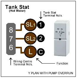
- Live = L (C)
- Switched Live 1 = SL1 (1)
- Switched Live 2 = SL2 (2)
Y Plan Room Stat Wiring
Room temperature thermostat wiring for room temperature control of the central heating system for Y Plan central heating systems.
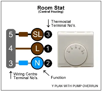
- Live = L (1)
- Neutral = N (2)
- Switched Live = SL (3)
Y Plan 3 Port Valve Connections
3 port mid position valve wiring colours and Y plan wiring center terminal numbers.

- Green/Yellow (Earth) = 2
- Blue (Neutral) = 3
- White = 5
- Grey = 7
- Orange = 8
Y Plan Boiler Connections
Y Plan boiler wiring diagram with pump overrun. Shown below first is the cable (function) followed by the terminal number of the Y plan wiring centre for system boiler wiring diagrams.

- Live = 1
- Earth = 2
- Neutral = 3
- Pump Live (PL) = 9
- Switched Live (SL) = 8
Y Plan Programmer Connections
Y plan central heating & hot water programmer wiring diagram, shown below first is the cable (function) followed by the terminal number of the Y plan wiring centre.
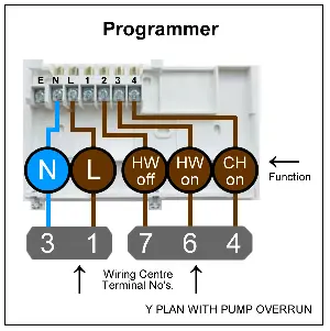
- Live (L) = 1
- Earth (⏚) = 2
- Neutral (N) = 3
- CH (on) = 4
- HW (on) = 6
- HW (off) = 7
Y Plan Power Connections
Y plan power supply connections, shown below first is the cable (function) followed by the terminal number of the Y plan wiring centre.
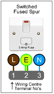
- Live = 1
- Earth = 2
- Neutral = 3
Download the App!
Download the Electrical Tools and Reference App for Android & iOS or get the desktop online version.


Y Plan Wiring Diagram

Note: Some earths have been omitted for clarity. Always check and follow the manufactures instructions as it may differ.
| Equipment & Function | Wiring Centre Terminal Number |
|---|---|
| SWITCHED FUSED SPUR | |
| Live | 1 |
| Earth | 2 |
| Neutral | 3 |
| BOILER | |
| Live | 1 |
| Earth | 2 |
| Neutral | 3 |
| Switched Live | 8 |
| Pump Live | 9 |
| PUMP | |
| Live | 9 |
| Earth | 2 |
| Neutral | 3 |
| 3 PORT VALVE | |
| Green/yellow | 2 |
| Blue | 3 |
| White | 5 |
| Grey | 7 |
| Orange | 8 |
| HOT WATER THERMOSTAT | |
| Live | 6 |
| Switched Live 1 | 8 |
| Switched Live 2 (HW Off) | 7 |
| CENTRAL HEATING THERMOSTAT | |
| Live | 4 |
| Neutral | 3 |
| Switched Live | 5 |
| PROGRAMMER | |
| Live | 1 |
| Earth | 2 |
| Neutral | 3 |
| HW Off | 7 |
| HW On | 6 |
| CH On | 4 |